SVS-Vistek GmbH today introduced its new fxo487 series of ultraviolet cameras with a maximum frame rate of 194 frames-per-second (fps) and 8.1MP resolution (2840 x 2840). The fastest model in the series features two CoaXPress-12 interfaces, which ensure quick and lossless transfer of the high data volumes generated as well as low trigger latency. In addition to CoaXPress-12 cameras, the series will be rounded out with an 10GigE interface version of the fxo487 that offers an economical, highly stable alternative with advantages for long data lines up to 100 meters.
New applications for UV imaging are emerging as more users integrate UV cameras into production environments such as pharmaceutical packaging, automotive parts, food processing, semiconductor manufacturing, factory automation, and electronic leakage detection. For example, the SVS-Vistek fxo487 is ideal for detecting pits, polish marks, and other defects on wafer surfaces, in the inspection of adhesives, and in locating scratches or digs on drivetrain components. It can also be applied in such diverse use cases as high-speed sorting of recycled materials, fluorescence analysis, plant monitoring, and in the examination of jewelry, glass, and liquids.
SVS-Vistek fxo487 cameras leverage the Sony IMX487-AAMJ-C CMOS sensor with a global shutter and variable charge-integration time. The sensor’s UV waveband (200nm to 400 nm) achieves high sensitivity and low dark current characteristics. Compact dimensions, combined with an operating temperature range of up to 60° C, help integrate the camera into space-sensitive applications and machines. In addition, its Industrial TTL-24V I/O interface offers the versatility of SafeTrigger, logic functions, programmable sequencers and timers, RS232 interface, and an integrated 4-channel strobe controller.
ISASecure Program Announces New ISASecure Certification Offering
Sept. 1, 2022 – The ISASecure program is announcing the new ISASecure certification offering for the industrial internet of things (IIoT) components based on the ISA/IEC 62443 series of standards.
The IIoT Component Security Assurance (ICSA) certification was inspired by recommendations published in the joint ISA Global Security Alliance (ISAGCA) and ISA Security Compliance Institute (ISCI) study. Details of this landmark study are available in the Learning Center section of the ISASecure website and were presented during our October 2021 webinar. The study and resulting ISASecure IIOT certification scheme address the urgent need for industry-vetted IIoT certification programs.
Join us on Sept. 7, 2022, at 11 a.m. ET for a live webinar where we will be presenting this important new certification offering. This webinar will provide an overview of the new ISASecure IIOT Device and Gateway certification program and its basis in the ISA/IEC 62443 set of industry standards. Register here.
About ISASecure
Founded in 2007, the ISA Security Compliance Institute’s (ISCI) mission is to provide the highest level of assurance possible for the cybersecurity of automation control systems. ISCI has been conducting ISASecure certifications on automation and control systems since 2011 through its network of ISO/IEC 17065 accredited certification bodies.
The Institute was established by thought leaders from major organizations in the automation controls community seeking to improve the cybersecurity posture of critical infrastructure for generations to come. Prominent ISASecure supporters include Chevron, ExxonMobil, Saudi Aramco, Shell, Honeywell, Schneider Electric, TUV Rheinland, Yokogawa, YPF, exida, GE Digital, Synopsis, CSSC, CSA Group, IPA-Japan, and others.
The Institute’s goals are realized through ISASecure compliance programs, education, technical support, and improvements in suppliers’ development processes and users’ life cycle management practices. The ISASecure designation ensures that automation products conform to industry consensus cybersecurity standards such as ISA/IEC 62443, providing confidence to users of ISASecure products and systems and creating product differentiation for suppliers conforming to the ISASecure specification.
About the International Society of Automation (ISA)
The International Society of Automation (ISA) is a non-profit professional association founded in 1945 to create a better world through automation. ISA advances technical competence by connecting the automation community to achieve operational excellence and is the trusted provider of standards-based foundational technical resources, driving the advancement of individual careers and the overall profession. ISA develops widely used global standards; certifies professionals; provides education and training; publishes books and technical articles; hosts conferences and exhibits; and provides networking and career development programs for its members and customers around the world.
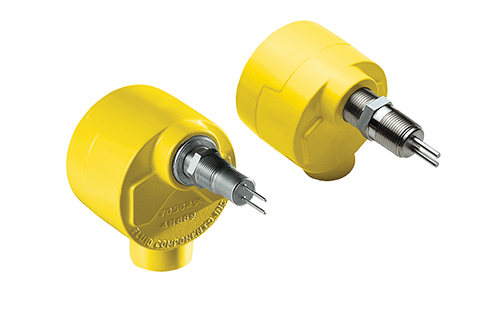
In high-temperature industrial environments, engineers responsible for optimizing the up-time and the safety of process flow networks will find the FLT93 Series Flow Switch from Fluid Components International (FCI) provides a reliable early warning alert to cooling tower pump dry-running conditions, which can lead to emergency shutdowns, service interruptions, pump failures, and unplanned costly maintenance.
For example, the high temperature, high-pressure distillation process environments encountered in crude oil refining process plants require the continuous cooling of the separation equipment with large cooling towers. These devices require the pumping of water-based coolant for air evaporative cooling or employ various coolant fluids designed to dissipate heat.
Large cooling towers draw hot air into the cooling tower and/or move air with large fans across and around equipment. Their water-based coolant is typically recycled and pumped multiple times and is treated with a variety of corrosion-inhibiting chemicals that protect both the cooling system and the equipment that is being cooled. In addition, to use in petrochemical plants, such cooling towers are also used in electric power generation plants and other industrial processes including the production of chemicals, food/beverage, and more.
Whatever type of active cooling tower system is in use at a plant, they all have several things in common. One of them, however, is essential for safety and throughput. Pumps are required to move the water and/or coolant fluid into the cooling tower. If a pump fails to move or replace the fluid in the cooling system or fails to recycle the fluid into the system, then equipment cooling is affected or disrupted. Similar to the way a leaky car radiator stops functioning, the driver (or in this case the plant control system or operator) sees the temperature gauge climbing fast: It’s time to pull over now and turn off the engine to avoid damage.
FCI’s dual alarm FLT93 Series Flow Switch reliably monitors the flow and temperature of liquids, gases, slurries, and more. It is ideal for pump wet/dry detection, where sudden, unexpected reductions in media flow rates can leave pumps vulnerable to over-heating conditions that shut down process lines and require troubleshooting, fixes, and more. This SIL2-rated instrument is designed for heavy-duty, potentially hazardous process industry environments and comes with a comprehensive list of global safety approvals.
With its no-moving parts design, the FLT93 Switch offers a highly robust scheme for pump protection with its dual alarm capability. With Alarm 1, the switch will detect a low flow situation anywhere between 0.01 and 3 feet per second FPS (0.003 to 0.9 meters per second MPS). This low flow alarm can be regarded as a pre-warning signal for the control system or operator. The system or operator can then decide to keep the pump running or shut it down.
Should an Alarm 2 occur because the feed line to the pump is running dry, this condition would be an emergency signal to shut down the pump immediately because the bearings now see gas instead of liquid as a heat transfer media. In such situations, the temperature of the bearings can rise very fast. Using a flow switch prevents permanent damage to the pump’s bearings that will require an overhaul of the pump before more damage occurs.
As a dual-function instrument that indicates both flow and temperature, and/or level sensing in a single device, the FLT93 Switch is a multipurpose component. Dual 6A relay outputs are standard and are assignable to flow, level or temperature. The FLT93 Switch can be specified in either insertion or inline styles for pipe or tube installation.
Ideal for rugged industrial applications, the FLT93 Switch is hydrostatically proof pressure tested to 3500 psig [240 bar (g)] at 70°F (21°C). De-rated with temperature, the maximum operation service recommended is 2350 psig [162 bar (g)] at 500°F (260°C). Higher ratings are available with special construction and test certification. Agency approvals include FM, FMc, ATEX, IECEx, SIL2, Inmetro, EAC/TR CU, CSA, CRN, and CE.
With superior dependability, FCI’s versatile FLT93 Switches are ideal for applications in many demanding process industries. They are also used extensively with or without SIL2 certification in a wide variety of applications in food/beverage, mining/milling, pulp/paper, pharmaceutical, water/wastewater treatment, and more.
Nord Drivesystems’ LogiDrive System Provides Optimized Solution Ideal for Intralogistics and Airports
The DuoDrive integrated gear unit and motor combine with the total LogiDrive package to form a high-efficiency solution capable of high-power density, quiet operation, and simple Plug-&-Play commissioning.
NORD’s LogiDrive complete drive solution reduces planning and commissioning efforts by offering an energy-efficient, standardized, and service-friendly system that is Industry 4.0 Ready! Permanent Magnet Synchronous Motor (PMSM) technology enables the LogiDrive system to maintain high efficiency even in partial load ranges and low speeds–making the solution especially suited for intralogistics, warehousing, and airport applications.
The LogiDrive package consists of:
High-efficiency two-stage bevel gearbox or DuoDrive
IE4 or IE5+ permanent magnet synchronous motor
Decentralized variable frequency drive
Power plug connector
M12 connectors
Incremental encoder
Pre-assembled cables
Standardized hollow shaft diameters
This solution reduces system variants through standardized geared motor selections tailored specifically to application needs and a large operable speed range via variable frequency drive technology. Simplifying engineering and selection into a compact, modular design significantly reduces spare parts inventory, enables fast commissioning through Plug-and-Play technology, and allows the replacement of individual components. The plug-in connections on the base product also enable easy maintenance, service, and installation.
When it comes to gearbox options for the LogiDrive package, two-stage helical bevel gear units or the new DuoDrive integrated gear unit and motor are available. Two-stage helical bevel gear units are made from high-strength aluminum alloy and feature an open housing option for better heat dissipation for high axial and radial loads. They excel in conveying and processing applications while providing a more efficient and reliable solution than typical worm units. The DuoDrive integrated gear unit and motor feature a compact, UNICASETM housing and deliver an extremely high gear efficiency of up to 92%. These drives also feature high power density, quiet operation, and fewer wear parts for low maintenance and long service life.
NORD’s IE4 and IE5+ synchronous motors provide some of the highest efficiencies currently available. The use of this technology in the LogiDrive system minimizes overall costs during service life, provides a faster return on investment, and maximizes system availability. When these motors are paired with the NORDAC LINK VFD, high precision regulation and increased system accuracy is achieved. This optimized combination also results in large overload capacities capable of constant torque over a wide speed range.
NORDAC LINK variable frequency drives offer quick installation and servicing thanks to their quick-disconnect cable options, integrated maintenance switch, and local manual control options. These decentralized VFDs feature functional safety options, an internal braking resistor for controlled, dynamic braking, and parametrization via plug-in control modules, NORDCON software, or NORDCON app. As part of the complete LogiDrive package, NORDAC LINK supports a large speed range–enabling automation for a variety of applications such as stacker cranes, automated transports, baggage handling systems, and conveyor systems.
The LogiDrive package provides a complete drive solution tailored to specific system needs. Not only does the modular design provide versatile arrangements, but it also reduces the number of variants, saves money in Total Cost of Ownership (TCO), and allows for each unit to be individually serviced–minimizing maintenance, downtime, and repair costs.
AW-Lake Offers Portable Flow Meter for On-Demand Pipe Flow Measurement without Process Interruptions
AW-Lake offers a new Portable Transit Time Ultrasonic Flow Meter in addition to the full-sized clamp-on version that provides non-contacting flow measurement for the most challenging industrial environments with minimal installation complexity and costs.
The new Portable Ultrasonic meter was designed to be deployed easily to measure flow on demand, without difficult installations or process interruptions.
The hand-held unit is encased in a rugged IP67 housing and works with the same 3 interchangeable transducers as the full-sized meter, which make it suitable for measurements on a wide range of metal and plastic pipe materials on pipes from ½” to 48” in diameter. A simple menu allows for fast and easy programming of pipe diameter, pipe material, liquid types, and measurement units. In addition to providing a standard 4-20mA/0-5V analog output, optional Modbus RTU and HART communications provide instantaneous flow rate, volume, total, run hours, and diagnostic information.
An intuitive on-screen user interface with a data logger enables operators to view flow reports or download logs for use in other programs. Data management storage of 12.5 million data points with logger software for data viewing and reporting. Through the use of an integrated USB-C port, the PTFM 6.1 seamlessly expands its input and output capability to meet future requirements without replacing the whole meter. The Greyline Portable Transit Time Flow Meter offers the versatility to meet changing flow measurement needs today, tomorrow, and into the future.
The flow meters use the transit time ultrasonic principle of measurement that works by measuring the flight difference for ultrasonic sound pulses transmitted from one transducer to another. The time between transmitted and received signals is precisely measured by the flow meters. Both Ultrasonic Flow Meters are ideal for measuring the flow rate of clean, non-aerated fluids in full pipes such as water, chemicals, and fuel oils with highly accurate and reliable flow measurement.
Sensor Integrity Ensures Temperature Measurement Accuracy
Although not every temperature application is a high-accuracy mea¬surement, best practices can be applied to eliminate sensor drift at the start of an installation. This helps users achieve optimal results while avoiding downtime or troubleshooting that might result from future drift during operation.
Several factors influence temperature system accuracy: individual sensor accuracy, extension wire, and measuring devices. When embarking on a project involving temperature measurement or control, consider these basic rules of thumb:
The same techniques used to achieve accuracy also result in curbing measurement drift.
Specifying the appropriate sensor will keep drift to a minimum.
Selecting the appropriate transmitter will keep drift from occurring.
Using 4-wire RTDs will eliminate the possibility of measurement drift. (Even if using direct-wired 3-wire RTDs, solutions exist to minimize lead wire drift.)
Reduction in drift means fewer calibrations/verifications, which translates to lowered operating expense.
Thermocouple extension wire decays over time, causing measurement error, in the form of drift, and requiring replacement.
Many of the considerations above have trivial impact on the initial purchase price and offer very significant impact on cost of ownership
The most common temperature sensors acceptable for temperature measurement and control include thermocouples, resistance temperature detectors (RTDs), thermistors, and semiconductor-based sensors. Only T/Cs, RTDs, and remote input/output (I/O) are discussed here.
Thermocouples
Thermocouples (T/Cs) are the most common temperature measurement sensors used in the U.S. for process control. T/C use is a proven technology in the industry. They are rugged, relatively inexpensive, and easy to use.
Figure 1: Solid sheath RTD or thermocouple temperature sensors.
When metals of different compositions come into contact, they form a junction that produces a voltage in the millivolt range. If the temperature to which this junction of dissimilar metals is exposed changes, there will be a corresponding change in the millivoltage produced by the junction.
Thermocouple types
Theoretically, any two different types of conductive material could be used to make a thermocouple. However, only a few combinations are used. The criteria for the material combinations chosen for use in thermocouples include the magnitude of their relative Seebeck coefficient, chemical stability, metallurgical stability, strength, ductility, and cost.
There are eight standard thermocouple types established in the U.S. The American National Standards Institute (ANSI) assigned letter designations to these eight types: T, J, K, E, N, S, R, and B (Table 1). The designations are based on the voltage versus temperature relationship for these thermocouples. The designations are not based on their compositions. T/Cs built to the ASTM E230 standard are more accurate. The ASTM E320 standard governs thermocouple accuracy.
T/C sensor accuracy
Thermocouple sensors built to the ASTM E230 standard are more accurate. The ASTM E320 standard governs thermocouple accuracy, as shown below in Table 2.
Premium/special grade thermocouple wire
Thermocouples can be constructed with premium- or special-grade wire that cuts uncertainty in half. The premium/special designation indicates that this wire has a higher purity alloy mix. Even with premium/special grade T/C, Moore Industries recommends using RTDs instead of T/ Cs whenever possible, as their accuracy, repeatability, and stability are superior to those of T/Cs. In comparing the accuracy data between Table 3 and Table 2, notice that the uncertainty is cut in half by using premium-grade sensors. If T/Cs must be used, premium grade offers greater stability at a negligible cost difference. The problem consistently seen in thermocouples is wire contami¬nation. As contamination occurs, error gradually increases to a point necessitating sensor replacement.
T/C extension wire characteristics
Anytime T/C extension wire is connected to a T/C, it introduces more uncertainty to the measurement (Table 4). If T/C extension wire will be exposed to temperatures outside the specified ranges, consider using actual thermocouple wire instead. In addition to uncertainty, T/C extension wire is susceptible to radio-frequency interference (RFI) and electromagnetic interference (EMI). Extension wire for J and K thermocouple types adds another ±2.2°C (±4.0°F) uncertainty when wire is clean and uncontaminated. Also, T/C extension wire tends to behave as an antenna for RFI and EMI. Use best practices to keep disruptive noise out of these low-level mV signals. T/C extension wire will degrade to the point of replacement; replacing it with more extension wire perpetuates the T/C extension wire replacement loop. However, premium-grade T/C extension wire cuts the potential error in half and should be selected.
If the extension wire is stressed by being exposed to temperatures outside the limits shown in Table 3, uncertainty will grow. Premium-grade extension wire still allows the possibility of error once metals become contaminated by airborne influences. It is recommended that T/C extension wire be eliminated as close to the T/C as possible by installing either temperature transmitters or remote I/O.
Options for eliminating T/C extension wire
Options exist that allow the elimination of T/C extension wire, thereby taking a step in ensuring reliable measurements. Among the options are temperature trans¬mitters, which can pose cost considerations, and remote I/O.
Temperature transmitters, remote I/O, and temperature concentrator modules eliminate expensive T/C and RTD extension wire and other point-to-point wires by sending temperature measurements, process monitoring, and control signals between the field and control room on one digital communication link. Related technologies, such as temperature concentrator modules (TCMs) and temperature transmitter/signal converters, have programmable inputs configurable for RTD, T/C, Ohms, mV or potentiometer, and current or voltage, depending on the specific module type. Outputs would often support HART, PROFIBUS PA, FOUNDATION Fieldbus, MODBUS RTU, etc.
Typical characteristics of state-of-the-art remote I/O include:
Minimum hazardous area certification of Class 1, Div. 2/Zone 2
Ambient temperature specs -40 to 85°C (-40 to 185°F)
Each input configured, calibrated, and custom-trimmed individually, as with temperature transmitters
A 20-bit input resolution and input accuracy equivalent to that of temperature transmitters
500 Vrms isolation in all directions
Sensor and I/O diagnostics
Serial, Ethernet, or wireless communication capability supporting open protocols such as MODBUS RTU, MODBUS/TCP, PROFINET, and EtherNet IP
Figure 2: Complete temperature assemblies using the WORM flexible sensor and an infinite combination of materials and components.
Resistance temperature detectors
RTD wire is a pure material, typically platinum, nickel, or copper. The material has an accurate resistance/temperature relationship, which is used to provide an indication of temperature. RTD elements are normally housed in stainless steel protective probes insulated and isolated from a protective sheath with magnesium oxide.
Common RTD sensing elements constructed of platinum, copper, or nickel have a repeatable resistance versus temperature relationship (R versus T) and operating temperature range. The R versus T relationship is defined as the amount of resistance change of the sensor per degree of temperature change. The relative change in resistance (temperature coefficient of resistance) varies only slightly over the useful range of the sensor.
Premium- and special-grade RTD sensors
Moore Industries thermally ages all of its RTDs to minimize drift once they get into the field. The RTDs are temperature cycled for 1,000 hours at 0° and 600°C, and will maintain accuracy for more than five years. Typically, only Class A sensors are thermally aged. Just as it is recommended that you use premium-grade T/C wire for thermo¬couple measurements, it is also suggested that you upgrade to Class A RTD sensors, which cuts uncertainty in half.
Sensor trimming for high accuracy
When a particular application demands the highest accuracy possible, Moore recommends ordering a temperature measurement system with bath calibration. A Class A RTD sensor is calibrated in a bath to calibrate it to the transmitter or remote I/O measuring device. This process eliminates the final “as-built” offset error that exists in every sensor. You then receive a NIST-traceable calibration report that indicates the combined sensor and temperature transmitter uncertainty, which is typically better than ±0.01°F.
Figure 3: The WORM RTD or thermocouple temperature flexible sensors with flex armor or stainless-steel braid covering the insulating jacket.
Effects of RTD extension wire on accuracy
The 1,000 Ω platinum RTD “secret.” If you must stay with 3-wire RTDs and you have long leads back to the DCS, consider replacing 100 Ω Pt RTDs with 1,000 Ω Pt RTDs. When this is done, the error caused by the resistance imbalance in the lead wire is reduced by a factor of 10.
Figure 4: By replacing 100 Ω Pt RTDs with 1,000 Ω Pt RTDs, the error caused by the resistance imbalance in the lead wire is reduced by a factor of 10.
Sensor selection summary
To optimize measurement performance and minimize long-term maintenance expenses, use the following guide for sensor selection:
Use an RTD when measuring in ranges between -40°C and 850°C (-40°F and 1562°F).
For temperatures as low as -200°C (-328°F), use a wire-wound RTD.
Best practice is to use 4-wire and Class A RTDs.
Make sure sensors are temperature cycled and “aged” for long-term stability.
When applying RTDs below 0°C and above 600°C, know the process conditions to optimize the build: temperature range, cycling, pressure, flow, media, vibration, and surrounding environmental conditions (chemicals/atmosphere).
When highest accuracy is needed, use sensor trimming.
If using 3-wire RTDs with long wire runs, and using 4-wire RTDs is not possible, replace the 3-wire RTDs with 1,000 Ω platinum RTDs.
For temperatures above 850°C (1,562°F), use thermocouples.
If using thermocouples, use premium-grade thermocouples and extension wire.
Make sure long thermocouple extension wire is noise protected.
Replace contaminated T/C extension wire with remote I/O.
Final thoughts
All temperature measurements, whether used for temperature indication or process control, begin with the sensor. Thermocouples and RTDs are the most common temperature sensors used in industrial applications. Temperature transmitters, remote I/O, and temperature concentrator modules eliminate expensive T/C and RTD extension wires and other point-to-point wires by sending temperature measurements, process monitoring, and control signals between the field and control room on a digital communication link.
When examining facilities and processes, users often see many opportunities for improved operation and efficiencies. They also might wonder how to better prepare their process for the next level of performance the future will inevitably require.
Fortunately, many locations are better prepared than they realize to seize opportunities for improvement and that the task of future-proofing is already done. The information many locations need could be hidden in plain sight. Stranded instrumentation data sits waiting to be used, connections among systems need waking up, and data connectivity and analysis tools reside within reach or are simple to add.
Data is closer than you think
Begin by looking at temperature and pressure instruments for data that could lead to efficiencies and savings. For example, some advanced temperature transmitters (Figure 1) provide additional information apart from the process temperature variables. They contribute diagnostic alerts that can be included in an ecosystem of insight, providing immediate benefit as they alert maintenance teams if the device, the sensor, or even the process needs attention.
Figure 1: Some advanced pressure transmitters provide additional information apart from the process variables.
In addition, a particular advanced digital sensor offers more than a single process measurement. The sensor simultaneously measures pressure and differential pressure, both of which can be accessed if one looks beyond the limiting factor of the 4-20 mA signal. The sensor data is abundant enough for algorithms or artificial intelligence (AI) to detect adverse process conditions such as pump cavitation or plugged impulse lines.
Data also can be found in devices that have been untouched for a while. Some field instruments are so reliable that they become “set and forget.” In some cases, that is the most economical solution, but realize that such an approach could leave value on the table. These forgotten devices may be the superstars of digital transformation efforts.
After reviewing the data the current devices provide, think about how that data can be best used. When eventually adding instrumentation, first consider how robust and reliable the devices are so they continue to give value for a long time. It is also imperative to measure their sophistication—the data they gather—so information continues to be harvested for future opportunities.
Tap into stranded data
Tapping into data collected by devices is important to the goal of process improvements. Standards such as HART communications and FDT technology can simplify the job.
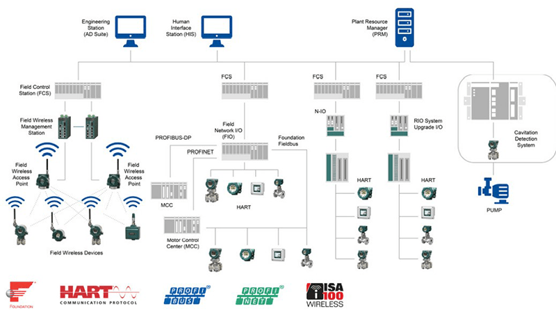
Communication standards. Communication protocols enable device interoperability, which means an array of devices from multiple suppliers can be used in a single facility often without the added expense of translating that data for each system using it. To help future-proof installations, look for devices that communicate using an open standard protocol (Figure 2). It is acceptable to have more than one standard in a given facility because many tools support multiple protocols. However, using too many different standards will place a greater burden on instrument and maintenance technicians.
Methods or mechanics. The mechanics required to tap into data range from straightforward to complex. Once the data is unlocked, the information can deliver benefits throughout the organization. Accessing stranded data is linked to one of three primary methods:
1. Native: When native communications are used, a simple license or software checkbox in the control system or data collector can begin the process of gathering information from field instruments. Though some system vendors charge an additional software license fee, this is usually trivial next to the simplicity of accessing the data.
Figure 2: Communication standards simplify device data integration.
2. Software: Data sharing sometimes requires users to add a software plugin to the system. These may be provided by the automation supplier or developed by a third-party software company. Older systems may require a custom solution, while newer systems rely more on standard protocols. FDT technology, for example, is an open standard for the integration of industrial automation networks and devices. Device suppliers provide a device type manager (DTM), which functions as a device driver to interpret information from the device.
3. Hardware: The third way to access data involves incorporating hardware such as gateways, multiplexers, or other edge devices. While the additional hardware and maintenance cost more, there are increased benefits to this approach. Dedicated hardware channels may provide faster communications than a native host system channel, which must prioritize control and safety data over asset performance and health.
Standard reduces data overload. Once the gates have been opened, a wealth of information is made available. Sometimes the amount of existing data can be overwhelming. Look to NAMUR NE107 for assistance. NE107 is a way to structure data into categories based on severity and simplify how data is delivered (Figure 3). NE107 helps users better understand an issue’s severity and helps users prepare appropriate responses.
Figure 3: Four categories from NE107 that simplify data organization.
An asset management system will be able to display alarms in the appropriate category, enabling technicians to recognize the severity of device alerts and take the necessary corrective actions. Due to innovations, many pressure and temperature devices—some possibly already in place— sort the data into NE107 categories: check function, maintenance required, out of spec, and failure. When used correctly, this information can improve operations and maintenance by helping technicians prioritize troubleshooting and repair work.
Put data to work
Once the data and the connections are set, plans can be created to put everything to work. Consider the facility’s improvement goals and what data could move the team toward them. For example, digital diagnostics help technicians troubleshoot existing issues. Predictive warnings provide early indications of impending failures so maintenance can be planned before the excess loss is realized. This type of data can reduce maintenance costs while improving plant availability and safety.
As data is being put into action, additional instrumentation and maintenance insights can help teams move from preventive to predictive maintenance. This means that device alerts will automatically report when a device needs attention. Technicians will no longer need to be sent out on monthly routes just to check device health.
For example, to promote continued reliable process operation and accuracy, users of certain advanced temperature sensors can set threshold and frequency limits to trigger an alarm status. This alarm can be used to estimate the remaining life of the sensor, allowing users to plan when maintenance would be most effective.
If using certain advanced multivariable sensors, users can put data to work in detecting line blockages. The fluctuations of differential and static pressure, and the capsule and ambient temperature signals are continuously monitored. Statistical calculations and comparison to reference conditions can show impulse line blockage.
Raw data from these devices also is more valuable than ever. In the past, case studies and failure analysis would guide software teams to develop algorithms allowing smart pressure and temperature transmitters to detect a specific issue or failure mode. Now artificial intelligence and machine learning (AI/ML) can replace these specific algorithms and begin detecting a wider range of potential conditions that may affect the process.
Note that users can choose from a wide variety of tools, from basic to high-end, that can help gather and analyze data. Open, enterprise-level asset management software for both automation and production assets can contribute to improving the quality of maintenance plans and optimizing maintenance costs throughout the plant lifecycle.
Imagine the changes, and plan the route As users discover the data and tools they already have—or make a few adjustments to obtain—they must think about the opportunities that await. As they plan their actions, they must look for robust instrumentation and tools that deliver performance today and continue to perform well into the future. Data is only accessible from a device that continues to operate reliably and communicates with the right protocols.
(Courtesy of ISA Automation and Author Nicholas Meyer)