Automatic compensation could be accomplished by intentionally inserting a temperature-dependent voltage source in series with the circuit, oriented in such a way as to oppose the reference junction’s voltage:

Vmeter = VJ1 − VJ2 + Vrjc
If the series voltage source Vrjc is exactly equal in magnitude to the reference junction’s voltage (VJ2), those two terms cancel out of the equation and lead to the voltmeter measuring only the voltage of the measurement junction J1:
Vmeter = VJ1 + 0; Vmeter = VJ1
This technique is known as hardware compensation and is employed in analog thermocouple temperature transmitter designs. A stand-alone circuit called an ice point, the purpose of which was to electrically counter the reference junction voltage as if that junction were immersed in a bath of ice water.
A modern technique for reference junction compensation more suitable to digital transmitter designs is called software compensation:
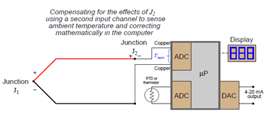
Instead of canceling the effect of the reference junction electrically, we cancel the effect arithmetically inside the microprocessor-based transmitter. In other words, we let the receiving analog-digital converter circuit see the difference in voltage between the measurement and reference junctions (Vinput = VJ1 − VJ2), but then after digitizing this voltage measurement we have the microprocessor add the equivalent voltage value corresponding to the ambient temperature sensed by the RTD or thermistor (Vrjc):
Compensated total = Vinput + Vrjc
Compensated total = (VJ1 − VJ2) + Vrjc
Since we know the calculated value of Vrjc should be equal to the real reference junction voltage (VJ2), the result of this digital addition should be a compensated total equal only to the measurement junction voltage VJ1:
Compensated total = VJ1 − VJ2 + Vrjc
Compensated total = VJ1 + 0
Compensated total = VJ1
The greatest advantage of software compensation is the flexibility to easily switch between different thermocouple types with no hardware modification. So long as the microprocessor memory is programmed with look-up tables relating voltage values to temperature values, it may accurately measure any thermocouple type. Hardware-based compensation schemes (e.g., an analog “ice point” circuit) require re-wiring or replacement to accommodate different thermocouple types since each ice-point circuit is built to generate a compensating voltage for a specific type of thermocouple.
Extension wire
In every thermocouple circuit, there must be both a measurement junction and a reference junction: this is an inevitable consequence of forming a complete circuit (loop) using dissimilar-metal wires. As we already know, the voltage received by the measuring instrument from a thermocouple will be the difference between the voltages produced by the measurement and reference junctions. Since the purpose of most temperature instruments is to accurately measure temperature at a specific location, the effects of the reference junction’s voltage must be “compensated” for by some means, either a special circuit designed to add an additional canceling voltage or by a software algorithm to digitally cancel the reference junction’s effect.
For reference junction compensation to be effective, the compensation mechanism must “know” the temperature of the reference junction. This fact is so obvious, it hardly requires mentioning. However, what is not so obvious is how easily this compensation may be unintentionally defeated simply by installing a different type of wire in a thermocouple circuit.
Like all modern thermocouple instruments, the panel-mounted indicator contains its own reference junction compensation, so that it is able to compensate for the temperature of the reference junction formed at its connection terminals, where the internal (copper) wires of the indicator join to the chromel and alumel wires of the thermocouple. The indicator senses this junction temperature using a small thermistor thermally bonded to the connection terminals.
A more economical alternative, however, is to use something called extension-grade wire to make the connection between the thermocouple and the receiving instrument. “Extension-grade” thermocouple wire is made less expensive than full “thermocouple-grade” wire by choosing metal alloys similar in thermo-electrical characteristics to the real thermocouple wires within modest temperature ranges. So long as the temperatures at the thermocouple head and receiving instrument terminals don’t get too hot or too cold, the extension wire metals joining to the thermocouple wires and joining to the instrument’s copper wires need not be precisely identical to the true thermocouple wire alloys. This allows for a wider selection of metal types, some of which are substantially less expensive than the measurement-grade thermocouple alloys. Also, the extension-grade wire may use insulation with a narrower temperature rating than thermocouple-grade wire, reducing the cost even further.
Extension-grade cable is denoted by a letter “X” following the thermocouple letter. For our hypothetical type K thermocouple system, this would mean type “KX” extension cable. Thermocouple extension cable also differs from thermocouple-grade (measurement) cable in the coloring of its outer jacket. Whereas thermocouple-grade cable is typically brown in exterior color, the extension-grade cable is usually colored to match the thermocouple plug (yellow for type K, black for type J, blue for type T, etc.).
What is burnout detection?
Another consideration for thermocouples is burnout detection. The most common failure mode for thermocouples is to fail open, otherwise known as “burning out.” An open thermocouple is problematic for any voltage-measuring instrument with high input impedance because the lack of a complete circuit on the input makes it possible for electrical noise from surrounding sources to be detected by the instrument and falsely interpreted as a wildly varying temperature.
For this reason, it is prudent to design into the thermocouple instrument some provision for generating a consistent state in the absence of a complete circuit. This is called the burnout mode of a thermocouple instrument. Only when the thermocouple fails open will the minuscule current through the resistor have any substantial effect on the voltmeter’s indication. The SPDT switch provides a selectable burnout mode: in the event of a burnt-out thermocouple, we can configure the meter to either read high temperature or low temperature (grounded), depending on what failure mode we deem safest for the application.
