One technique is to physically fix the temperature of that junction at some constant value, so it is always stable. This way, any changes in measured voltage must be due to changes in temperature at the measurement junction since the reference junction has been rendered incapable of changing temperature. This may be accomplished by immersing the reference junction in a bath of ice and water:
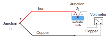
In fact, this is how thermocouple temperature/voltage tables are referenced: describing the amount of voltage produced for given temperatures at the measurement junction with the reference junction held at the freezing point of water. With the reference junction maintained at the freezing point of water and thermocouple tables referenced to that specific cold junction temperature, the voltmeter’s indication will simply and directly always correspond to the temperature of measurement junction J1.
However, fixing the reference junction at the temperature of freezing water is impractical for any real thermocouple application outside of a laboratory. Instead, we need to find some other way to compensate for changes in reference junction temperature, so that we may accurately interpret the temperature of the measurement junction despite random changes in reference junction temperature.
A practical way to compensate for the reference junction voltage is to include an additional voltage source within the thermocouple circuit equal in magnitude and opposite in polarity to the reference junction voltage. If this additional voltage is made continually equal to the reference junction’s potential, it will precisely counter the reference junction voltage, resulting in the full (measurement junction) voltage appearing at the measuring instrument terminals. This is called a reference junction compensation or cold junction compensation circuit:
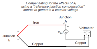
For such a compensation strategy to work, the compensating voltage must continuously track the voltage produced by the reference junction. To do this, the compensating voltage source (Vrjc in the above schematic) uses some other temperature-sensing device such as a thermistor or RTD to sense the local temperature at the terminal block where junction J2 is formed and produce a counter-voltage that is precisely equal and opposite to J2’s voltage (Vrjc = VJ2) at all times. Having canceled the effect of the reference junction, the voltmeter now only registers the voltage produced by the measurement junction J1:
Vmeter = VJ1 − VJ2 + Vrjc
Vmeter = VJ1 + 0 (If Vrjc = VJ2)
Vmeter = VJ1
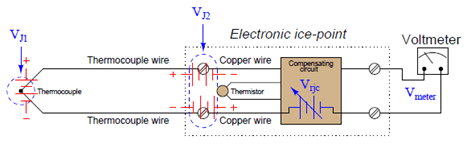
This compensating voltage is maintained at the proper value according to the terminal temperature where the thermocouple wires connect to the ice point module, sensed by a thermistor or RTD:
Thermocouples are extremely rugged and have far greater temperature measurement ranges than thermistors, RTDs, and other primary sensing elements. However, if the application does not demand extreme ruggedness or large measurement ranges, a thermistor or RTD is probably the better choice!
The presence of reference junction compensation becomes quite troublesome, for example, if one tries to simulate a thermocouple using a precision millivoltage source. Simply setting the millivoltage source to the value corresponding to the desired (simulation) temperature given in a thermocouple table will yield an incorrect result for any ambient temperature other than the freezing point of water!
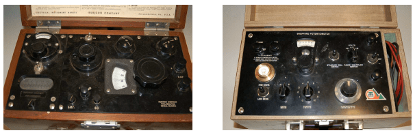
The only suitable piece of test equipment available for generating the precise millivoltage signals necessary to calibrate thermocouple instruments was a device called a precision potentiometer. These “potentiometers” used a stable mercury cell battery (sometimes called a standard cell) as a voltage reference and a potentiometer with a calibrated knob to output low voltage signals.
