Generally known as the Kelvin or four-wire method employed to make precise resistance measurements. The four-wire technique uses four wires to connect the resistance under test (in this case, the RTD) to the measuring instrument. Two wires carry “excitation” current to the RTD from a current source, while the other two wires merely “sense” voltage drop across the RTD resistor element and carry that voltage signal to a voltmeter:
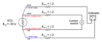
Wire resistances are completely inconsequential in this circuit. The two “excitation” wires carrying current to the RTD will drop some voltage along their length, but this voltage drop is only “seen” by the current source and not the voltmeter. The two “sense” wires connecting the voltmeter to the RTD also, possess resistance, but they drop negligible voltage because the voltmeter draws so little current through them. Thus, the resistances of the current-carrying wires are of no effect because the voltmeter never senses their voltage drops and the resistances of the voltmeter’s sensing wires are of no effect because they carry practically zero current.
The only disadvantage of the four-wire method is the sheer number of wires necessary. Four wires per RTD can add up to a sizeable wire count when many different RTDs are installed in a process area. Wires cost money and occupy expensive conduits, so there are situations where the four-wire method is a burden.

It is critically important to note that the common connections shown by the symbols for 3- and 4-wire RTD sensors represent junction points at the sensor; not terminals jumpered by the technician at the time of installation, and not internal jumpers inside the transmitter. The whole purpose of having 3-wire and 4-wire RTD circuits is to eliminate errors due to voltage drops along the current-carrying wires, and this can only be realized if the “sensing” wire(s) extend out to the RTD itself and connect there. If the transmitter’s sensing terminal(s) are only jumpered to a current-carrying terminal, the transmitter will sense voltage dropped by the RTD plus voltage dropped by the current-carrying wire(s), leading to falsely high-temperature indications.
Always bear in mind the purpose of a 3-wire or a 4-wire RTD connection: to avoid inaccuracies caused by voltage drops along the current-carrying wires. The only way to do this is to ensure the sensing (non-current carrying) wire(s) extend from the transmitter terminal(s) all the way to the sensor itself. This way, the transmitter can “look past” the voltage drops of the current-carrying wires to “see” the voltage dropped only by the RTD itself.
