A compromise between two-wire and four-wire RTD connections is the three-wire connection, which looks like this:
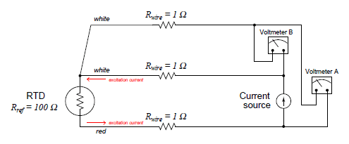
In a three-wire RTD circuit, voltmeter “A” measures the voltage dropped across the RTD plus the voltage dropped across the bottom current-carrying wire. Voltmeter “B” measures just the voltage dropped across the top current-carrying wire. Assuming both current-carrying wires will have (very nearly) the same resistance, subtracting the indication of voltmeter “B” from the indication given by voltmeter “A” yields the voltage dropped across the RTD:
VRTD = Vmeter(A) − Vmeter(B)
If the resistances of the two current-carrying wires are precisely identical (and this includes the electrical resistance of any connections within those current-carrying paths, such as terminal blocks), the calculated RTD voltage will be the same as the true RTD voltage, and no wire-resistance error will appear. If, however, one of those current-carrying wires happens to exhibit more resistance than the other, the calculated RTD voltage will not be the same as the actual RTD voltage, and a measurement error will result.
Thus, we see that the three-wire RTD circuit saves us wire cost over a four-wire circuit, but at the “expense” of a potential measurement error. The beauty of the four-wire design was that wire resistances were completely irrelevant: a true determination of RTD voltage (and therefore RTD resistance) could be made regardless of how much resistance each wire had, or even if the wire resistances were different from each other. The error-canceling property of the three-wire circuit, by contrast, hinges on the assumption that the two current-carrying wires have exactly the same resistance, which may or may not actually be true.
A practical electronic circuit for a 3-wire RTD sensor is shown here (differential voltages shown in blue, ground-referenced voltages shown in red):

Note that the voltage appearing at point B about the ground is the RTD’s voltage plus the voltage dropped by one of the two current-carrying wires: VRTD + Verror. It is this “error” voltage we must eliminate to achieve an accurate measurement of RTD voltage drop, essential for accurately inferring RTD temperature. The voltage appearing at point A is greater by one more wire’s voltage drops (Verror + VRTD + Verror) because that point spans one more wire resistance in the circuit than point B.
Like all negative-feedback operational amplifier circuits allow the amplifier to maintain the two input terminals at (nearly) the same voltage. Thus, the voltage at point B is duplicated at the inverting input terminal by the amplifier’s feedback action. From this, we may see that the voltage drop across the left-hand 100 kΩ resistors is simply Verror: the potential difference between point A and point B. The feedback current driving through this resistor goes through the other 100 kΩ feedback resistor equally, causing the same voltage drop to appear there (Verror). We may see that the polarity of this second resistor’s voltage drop ends up subtracting that quantity from the voltage appearing at the inverting input terminal. The inverting terminal voltage (VRTD + Verror) minus the right-hand 100 kΩ resistor’s voltage drop (Verror) is simply VRTD, and so the voltmeter registers the true RTD voltage drop without any wire resistance error.
Like the two-voltmeter circuit shown previously, this amplified 3-wire RTD sensing circuit “assumes” the two current-carrying wires will have the exact same resistance and therefore drop the same amount of voltage. If this is not the case, and one of these wires drops more voltage than the other, the circuit will fail to yield the exact RTD voltage (VRTD) at the amplifier output. This is the fundamental limitation of any 3-wire RTD circuit: the cancellation of wire resistance is only as good as the wires’ resistances are precisely equal.
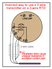
3-wire RTD measurement assumes that both current-carrying wires have the same electrical resistance. By paralleling two of the four wires in the 4-wire cable, you will create unequal resistances in the current path, thus leading to measurement errors at the transmitter.
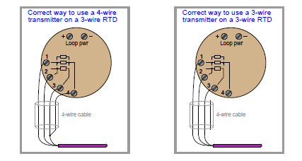
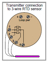
Better solutions for the 3-wire RTD and 4-wire cable scenario include configuring the transmitter for 4-wire RTD input and using all four terminals (shown on left), or keeping the transmitter configured for 3-wire RTD input and not using the fourth wire in the cable at all (shown on right).
