This section does not describe a particular type of flowmeter, but rather a design that may be implemented for several different kinds of flow measurement technologies. When the pipe carrying process fluid is large in size, it may be impractical or cost-prohibitive to install a full-diameter flowmeter to measure fluid flow rate. A practical alternative for many applications is the installation of an insertion flowmeter: a probe that may be inserted into or extracted from a pipe, to measure fluid velocity in one region of the pipe’s cross-sectional area (usually the center).
A classic example of an insertion flowmeter element is the Annubar, a form of averaging pitot tube pioneered by the Dieterich Standard corporation. The Annubar flow element is inserted into a pipe carrying fluid where it generates a differential pressure for a pressure sensor to measure:
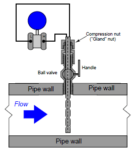
The Annubar element may be extracted from the pipe by loosening a “gland nut” and pulling the assembly out until the end passes through a hand ball valve. Once the element has been extracted this far, the ball valve may be shut and the Annubar completely removed from the pipe:

For safety reasons, a “stop” is usually built into the assembly to prevent someone from accidentally pulling the element all the way out with the valve still open.
Other flowmeter technologies manufactured in insertion form include vortex, turbine, and thermal mass. An insertion-type turbine flowmeter appears in the following photographs:

If the flow-detection element is compact rather than distributed (as is certainly the case with the turbine flowmeter shown above), care must be taken to ensure correct positioning within the pipe. Flow profiles are never completely flat, any insertion meter element will register a greater flow rate at the center of the pipe than near the walls. Wherever the insertion element is placed in the pipe diameter, that placement must remain consistent through repeated extractions and re-insertions, or else the effective calibration of the insertion flowmeter will change every time it is removed and re-inserted into the pipe. Care must also be taken to insert the flowmeter so the flow element points directly upstream, and not at an angle.
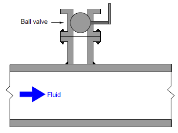
A unique advantage of insertion instruments is that they may be installed in an operating pipe by using specialized hot-tapping equipment. A “hot tap” is a procedure whereby a safe penetration is made into a pipe while the pipe is carrying fluid under pressure. The first step in a hot-tapping operation is to weld a “saddle tee” fitting on the side of the pipe:

Next, a ball valve is bolted onto the saddle tee flange. This ball valve will be used to isolate the insertion instrument from the fluid pressure inside the pipe:
A special hot-tapping drill is then bolted to the open end of the ball valve. This drill uses a high-pressure seal to contain fluid pressure inside the drill chamber as a motor spins the drill bit. The ball valve is opened, then the drill bit is advanced toward the pipe wall where it cuts a hole into the pipe. Fluid pressure rushes into the empty chamber of the ball valve and hot-tapping drill as soon as the pipe wall is breached:

Once the hole has been completely drilled, the bit is extracted and the ball valve shut to allow removal of the hot-tapping drill:

Now there is a flanged and isolated connection into the “hot” pipe, through which an insertion flowmeter (or another instrument/device) may be installed.
Hot-tapping is a technical skill, with many safety concerns specific to different process fluids, pipe types, and process applications. This brief introduction to the technique is not intended to be instructional, but merely informational.
Process/instrument suitability
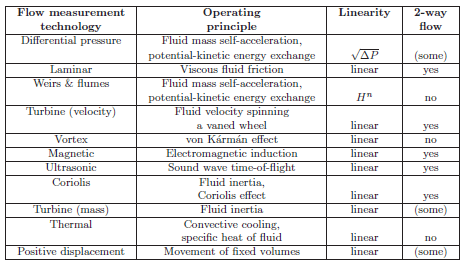
Every flow-measuring instrument exploits a physical principle to measure the flow rate of the fluid stream. Understanding each of these principles as they apply to different flow-measurement technologies is the first and most important step in properly applying a suitable technology to the measurement of a particular process stream flow rate. The following table lists the specific operating principles exploited by different flow measurement technologies:
A potentially important factor in choosing an appropriate flowmeter technology is energy loss caused by pressure drop. Some flowmeter designs, such as the common orifice plate, are inexpensive to install but carry a high price in terms of the energy lost in permanent pressure drop (the total, non-recoverable loss in pressure from the inlet of the device to the outlet, not the temporary pressure difference between inlet and vena contracta). Energy costs money, and so industrial facilities would be wise to consider the long-term cost of a flowmeter before settling on the one that is cheapest to install. It could very well be, for example, that an expensive venturi tube will cost less after years of operation than a cheap orifice plate. In this regard, certain flowmeters stand above the rest: those with obstruction-less flow tubes. Magnetic and ultrasonic flowmeters have no obstructions whatsoever in the path of the flow. This translates to (nearly) zero permanent pressure loss along the length of the tube, and therefore. Thermal mass and straight-tube Coriolis flowmeters are nearly obstruction less, while vortex and turbine meters are only slightly worse.
List of Prominent Suppliers: ABB, Baker Hughes, Burkert, Comate, CS Instruments, DropsA, Dwyer, E+E, Endress + Hauser, Flomec, FlowTech, Flow-Tronic, Fluid Components International, Gavin, GHM Group, Hach, Holykell, ISOIL, Kobold, McCrometer, MC Techgroup, Mecon, Metri, Omega, Oval, Praher Plastics, Primayer, Prisma, Pulsar, Q&T, Sierra, Solidat, Supmea, Tecfluid, Teledyne, Thermo Scientific, Titan, VP Instruments, Weber
