Springs work quite nicely to convert mechanical force into mechanical motion (Hooke’s Law – F = kx) for valve actuators if and only if the sole forces involved are the diaphragm or piston force against the spring’s resistance force. If any other force acts upon the system, the relationship between actuating fluid pressure and valve stem travel will not necessarily be proportional.
Unfortunately, there typically are other forces acting on a valve stem beside the actuating fluid pressure’s force and the spring’s reaction force. Friction from the stem packing is one force, and the reaction force at the valve plug caused by differential pressure across the plug’s area is another. These forces conspire to re-position the valve stem so stem travel does not precisely correlate to actuating fluid pressure.
A common solution to this dilemma is to add a positioner to the control valve assembly. A positioner is a motion-control device designed to actively compare stem position against the control signal, adjusting pressure to the actuator diaphragm or piston until the correct stem position is reached:
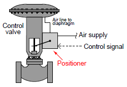
Positioners essentially act as control systems within themselves15: the valve’s stem position is the process variable (PV), the command signal to the positioner is the setpoint (SP), and the positioner’s signal to the valve actuator is the manipulated variable (MV) or output. Thus, when a process controller sends a command signal to a valve equipped with a positioner, the positioner receives that command signal and applies as much or as little air pressure to the actuator as needed in order to achieve that desired stem position. Thus, the positioner will “fight” against any other forces acting on the valve stem to achieve crisp and accurate stem positioning according to the command signal. A properly functioning positioner ensures that the control valve will be “well-behaved” and obedient to the command signal.
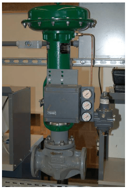
The following photograph shows a Fisher model 3582 pneumatic positioner mounted to a control valve. The positioner is the grey-colored box with three pressure gauges on the right-hand side:
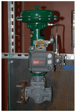
A more modern positioner appears in the next photograph, the Fisher DVC6000 (again, the grey-colored box with pressure gauges on the right-hand side):
Control valve positioners are typically constructed in such a way as to source and vent high air flow rates, such that the positioner also fulfills the functionality of a volume booster. Thus, a positioner not only ensures more precise valve stem positioning but also faster stem velocity (and shorter time delays) than if the valve actuator were directly “powered” by an I/P transducer.
Another advantage of adding a positioner to a pneumatically actuated control valve is superior valve seating (tight shutoff). This benefit is not obvious at first inspection, and so some explanation is in order.
First, one must understand that mere contact between the plug and seat within a sliding-stem valve is not enough to ensure a tight shut-off. Rather, the plug must be forcefully pressed down onto the seat in order to fully shut off all flow through the valve. Anyone who has ever tightened the handle on a leaking hose bib (garden spigot) intuitively understands this principle: a certain amount of contact force between the plug and the seat is necessary in order to slightly deform and thereby mold those two components to a perfect fluid-tight fit. The technical term for this mechanical requirement is seat load.
Imagine if you will a diaphragm-actuated, sliding-stem, air-to-open control valve with a bench set range of 3 to 15 PSI. At an applied actuator pressure of 3 PSI, the diaphragm generates just enough force to exactly overcome the actuator spring’s pre-load force, but not enough force to actually move the plug off the seat. In other words, at 3 PSI diaphragm pressure, the plug is touching the seat but with little or no force to provide a tight shut-off seal. If this control valve is directly powered by an I/P transducer with a 3-15 PSI calibrated range, it means the valve will be barely shut at a 0% signal value (3 PSI) rather than tightly shut off. In order to full force the valve plug against the valve seat to achieve a tight seal, all air pressure would have to be vented from the diaphragm so that there is no diaphragm force opposing the spring. This is impossible with an I/P having a calibrated range of 3-15 PSI.
Now imagine that exact same valve equipped with a positioner, taking the 3-15 PSI signal from the I/P and using it as a command (setpoint) for valve stem position, applying as much or as little pressure to the diaphragm as necessary to achieve the desired stem position. Proper positioner calibration is such that the valve stem does not begin to lift until the signal has risen slightly above 0%, which means at 0% (4 mA) the positioner will be trying to force the valve to a slightly negative stem position. In attempting to achieve this impossible demand, the positioner’s output will saturate low, applying no pressure whatsoever to the actuating diaphragm, resulting in full spring force applied by the plug against the seat. A comparison of the two scenarios is shown here:

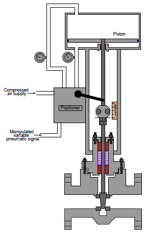
While positioners are beneficial on spring-equipped valve actuators, they are absolutely essential for some other styles of actuators. One example of an actuator requiring a positioner for proper operation is the springless, double-acting pneumatic piston actuator, shown here in this cutaway illustration actuating a gate valve body with a positioner attached:
Electric control valve actuators are another class of actuator design absolutely requiring some form of positioner system because an electric motor is not “aware” of its own shaft position in order that it may precisely move a control valve. Thus, a positioner circuit using a potentiometer or LVDT/RVDT sensor to detect valve stem position and a set of transistor outputs to drive the motor is necessary to make an electric actuator responsive to an analog control signal.
