Arguably, the component most critical to measurement accuracy in a gas chromatograph is the sample valve. Its purpose is to inject the exact same sample quantity into the column at the beginning of each cycle. If the sample quantity is not repeatable, the measured quantities exiting the column will change from cycle to cycle even if the sample composition does not change. If the valve’s cycle time is not repeatable, component separation efficiency will vary from cycle to cycle. If the sample valve leaks such that a small flow rate of sample continuously enters the column, the result will be an altered “baseline” signal at the detector (at best) and total corruption of the analysis (at worst). Many process chromatograph problems are caused by irregularities in the sample valve(s).
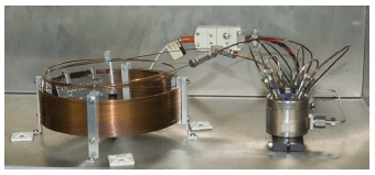
A photograph of the column (coil of fine tubing, on the left) and sample valve (stainless-steel cylinder with several tubes entering and exiting, on the right) for a gas chromatograph appears here:
A common form of sample valve uses a rotating element to switch port connections between the sample gas stream, carrier gas stream, and column:
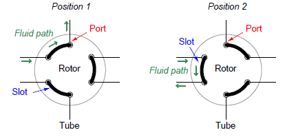
Three slots connect three pairs of ports together. When the rotary valve actuates, the port connections switch, redirecting gas flows.
Connected to a sample stream, carrier stream, and column, the rotary sample valve operates in two different modes. The first mode is a “loading” position where the sample stream flows through a short length of tubing (called a sample loop) and exits to a waste discharge port, while the carrier gas flows through the column to wash the last sample through. The second mode is a “sampling” position where the volume of sample gas held in the sample loop tubing gets injected into the column by a flow of carrier gas behind it:


The purpose of the sample loop tube is to act as a holding reservoir for a fixed volume of the sample gas. When the sample valve switches to the sample position, the carrier gas will flush the contents of the sample loop into the front of the column. This valve configuration guarantees that the injected sample volume does not vary with inevitable variations in sample valve actuation time. The sample valve need only remain in the “sampling” position long enough to completely flush the sample loop tube, and the proper volume of the injected sample gas is guaranteed.

While in the loading position, the stream of gas sampled from the process continuously fills the sample loop and then exits to a waste port. This may seem unnecessary, but it is in fact essential for practical sampling operations. The volume of process gas injected into the chromatograph column during each cycle is so small (typically measured in units of microliters!) that a continuous flow of sample gas to waste is necessary to purge the impulse line connecting the analyzer to the process, which in turn is necessary for the analyzer to obtain analyses of current conditions. If it were not for the continuous flow of samples to waste, it would take a very long time for a sample of process gas to make its way through the long impulse tube to the analyzer to be sampled!
