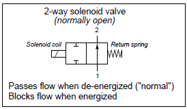
Solenoid valve symbols often appear identical to fluid power valve symbols, with “boxes” representing flow paths and directions between ports in each of the valve’s states. Like electrical switches, these valve symbols are always drawn in their “normal” (de-energized) state, where the return spring’s action determines the valve position:
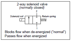
A good way to make sense of these “box” valve symbols is to imagine the boxes sliding back and forth as the actuating elements work. For example, the two boxes in a normally closed solenoid valve symbol may be thought of as pushed to one side by the spring (in its de-energized state) and pushed the other direction by the solenoid’s force (when energized). Here, the color grey de-emphasizes the unselected box in each of the valve’s two states:

Just like electrical switches in schematic diagrams, fluid control valve symbols are always drawn in their “normal” (resting) states. For example, a normally closed valve will always be drawn so that the box with the blocked ports aligns with the tubes leading to and from the valve. What you see in the above illustration is a “dramatized” symbol, highlighting the valve’s action by color and by re-positioning the boxes. In a fluid control schematic, it is left to the reader to visualize the valve symbol boxes moving to and fro, determining the flow path of fluid through the valve.
Unlike electrical switches, of course, the terms open and closed have opposite meanings for valves. An “open” electrical switch constitutes a break in the circuit, ensuring no current; an “open” valve, by contrast, freely allows fluid to flow through it. A “closed” electrical switch has continuity, allowing current through it; a “closed” valve, on the other hand, shuts off fluid flow.
The arrow inside a solenoid valve symbol denotes a preferred direction of flow. Most solenoid valves use a “globe” or “poppet” style of the valve element, where a metal plug covers up a hole (called the “seat”). Process fluid pressure should be applied to the valve in such a way that the pressure difference tends to hold the solenoid valve in its “normal” position (the same position as driven by the return spring). Otherwise, enough fluid pressure might override the return spring’s action, preventing the valve from achieving its “normal” state when de-energized. Thus, we see that the label “2-way” does not refer to two directions of flow as one might assume, but rather two ports on the valve for fluid to travel through.
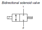
Some solenoid valves are designed so that the direction of fluid flow through them is irrelevant. In such valves, the arrow symbols will be double-headed (one head at each end, pointing in opposite directions) to show the possibility of flow in either direction.
