A very common form of on/off valve used for pneumatic and hydraulic systems is the solenoid valve. A “solenoid” is nothing more than a coil of wire designed to produce a magnetic field when energized. Solenoid actuators work by attracting a movable iron armature into the center of the solenoid coil when energized, the force of this attraction working to actuate a small valve mechanism.
Solenoid-actuated valves are usually classified according to the number of ports (“ways”). A simple on/off solenoid valve controlling flow into one port and out of another port is called a 2-way valve. Another style of the solenoid valve, where flow is directed in one path or to another, much like a single-pole double-throw (SPDT) electrical switch, is called a 3-way valve because it has three fluid ports.
Normal energization states
Solenoid valves may be used in such a way that they spend most of their time de-energized, energizing only for brief periods of time when some special function is required. Alternatively, solenoids may be maintained in an energized state, and de-energized to perform their design function. The choice to use a solenoid’s energized or de-energized state to perform a specific function is left to the system designer, but nevertheless, all maintenance personnel needs to know to perform work on a solenoid-controlled system.
Take the following segment of an actual P&ID for a steam turbine-driven pump control system for example, where a pair of 3-way solenoid valves control instrument air pressure to a piston-actuated steam valve to start the turbine if an electric motor-driven pump happens to fail:
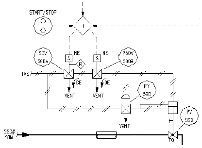
If either of the two solenoid valves de-energizes, instrument air pressure will vent from the top of the piston actuator to the atmosphere, causing the steam valve to “fail” to the full-open position and send steam to the turbine. This much is evident from the curved arrows showing air flowing to the “Vent” ports in a de-energized (DE) condition. An additional valve (PY-590) guarantees the piston actuator’s an upward motion by simultaneously applying air pressure to the bottom of the actuator if ever air is vented from the top. As an additional feature, the left-hand solenoid valve (SOV-590A) has a manual “Reset” lever on it, symbolized by the letter “R” inside a diamond outline.
The only indication of the solenoids’ typical status (energized or de-energized) comes from the letters “NE” next to each solenoid coil. In this case, “NE” stands for normally energized. Therefore, this steam turbine control system, which serves as a backup to an electric motor-driven pump, relies on either (or both) of the solenoid valves de-energizing to make the turbine start up. Under “normal” conditions, where the turbine is not needed, the solenoids remain energized, and the steam valve remains shut.
Unfortunately, this use of the word “normal” is altogether different from the use of the word “normal” when describing a solenoid valve’s open/close characteristics. Recall that a normally open solenoid valve allows fluid to pass through when it is de-energized. A normally closed solenoid valve, by contrast, shuts off fluid flow when de-energized. In this context, the word “normally” refers to the unpowered state of the solenoid valve. This is quite similar to how the word “normally’ is used to describe switch contact status: a normally open (NO) electrical switch is open when unactuated (at rest); a normally closed (NC) electrical switch is closed when unactuated (at rest). In both cases, with solenoid valves and with electrical switches, the word “normally” refers to the resting condition of no stimulation.
However, when an engineer designs a solenoid control system and declares a solenoid to be “normally energized,” that engineer is describing the typical status of the solenoid valve as it is intended to function in the process. This may or may not correspond to the manufacturer’s definition of “normally,” since the solenoid manufacturer cannot possibly know which state any of their customers intends to have their solenoid valve typically operate in. To illustrate using the previous steam turbine control system P&ID, those two solenoid valves would be considered normally closed by the manufacturer, since their de-energized states block airflow from the “P” port to the “C” port and vent air pressure from the “C” port to the “E” (vent) port. However, the engineer who designed this system wanted both solenoids to be energized whenever the turbine was not needed to run (the “normal” state of the process), and so the engineer labeled both solenoid coils as normally energized, which means both solenoids will be actuated to pass air pressure from their “P” ports to their “C” ports (and close off the vent ports) under typical conditions. Here, we see the manufacturer’s definition of “normal” is precisely opposite that of the process engineer’s definition of “normal” for this application. should only connect to the bottom of the piston actuator, not to the bottom and the top. A more minor error in this diagram snippet is the labeling of SOV-590A: it reads “SOV-59DA” if you look closely enough! My first inclination when sampling this real P&ID for inclusion in the book was to correct the errors, but I think an important lesson may be taught by leaving them in: documentation errors are a real challenge you will contend with on the job as an instrumentation professional!
The manufacturer’s and process engineer’s definitions of “normally” are not always in conflict. Take for example this P&ID segment, showing the solenoid control of an air vent door on a large furnace, designed to open if the forced-draft fan (blowing combustion air into the furnace) happens to stop for any reason:
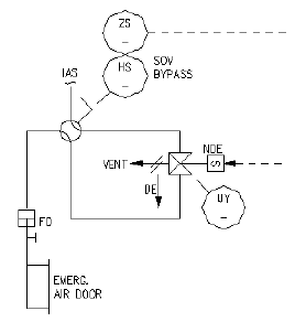
Here we have a normally open solenoid valve, designed by the manufacturer to pass instrument air pressure from the pressure (“P”) port to the cylinder (“C”) port when de-energized. The straight arrow with the “DE” label next to it reveals this to be the case. Instrument air pressure sent to the air door actuator holds the door shut, meaning the air door will swing open if ever instrument air pressure is vented by the solenoid. For this solenoid, this would require an energized condition.
The process engineer designing this Emergency Air Door control system choose to operate the solenoid in its de-energized state under typical operating conditions (when the furnace air door should be shut), a fact revealed by the letters “NDE” (normally de-energized) next to the solenoid coil symbol. Therefore, the “normal” process operating condition for this solenoid happens to be de-energized, which makes the manufacturer’s definition of “normal” match the engineer’s definition of “normal.” The solenoid valve should be open (passing air to the door’s actuating cylinder) under “normal” operating conditions.
