Motor control circuit wiring
A simple three-phase, 480-volt AC motor-control circuit is shown here, both in pictorial and schematic form. This entire assembly consisting of a contactor, overload block, control power transformer, power fuses (or alternatively, a circuit breaker), and associated components are informally referred to as a bucket:

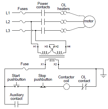
Note how a control power transformer steps down the 480-volt AC to provide 120-volt AC power for the contactor coil to operate on. Furthermore, note how the overload (“OL”) contact is wired in series with the contactor coil so that a thermal overload event forces the contactor to de-energize and thus interrupt power to the motor even if the control switch is still in the “on” position. The overload heaters appear in the schematic diagram as pairs of back-to-back “hook” shapes, connected in series with the three “T” lines of the motor. Remember that these “OL” heater elements do not directly interrupt power to the motor in the event of an overload, but rather signal the “OL” contact to open and de-energize the contactor.
In an automatic control system, the toggle switch would be replaced by another relay contact (that relay is controlled by the status of a process), a process switch, or perhaps the discrete output channel of a programmable logic controller (PLC).
It should be noted that a toggling-style of the switch is necessary for the motor to continue to run after a human operator actuates the switch. The motor runs with the switch in the closed state and stops when the switch opens. An alternative to this design is to build a latching circuit allowing the use of momentary contact switches (one to start, and one to stop). A simple latching motor control circuit is shown here:

In this circuit, an auxiliary contact actuated by the motor contactor is wired in parallel with the “Start” pushbutton switch, so that the motor contactor continues to receive power after the operator releases the switch. This parallel contact – sometimes called a seal-in contact – latches the motor in an “on” state after a momentary closure of the “Start” pushbutton switch.
A normally closed “Stop” switch provides a means to “un-latch” the motor circuit. Pressing this pushbutton switch stops current in the coil of the contactor, causing it to de-energize, which then opens the three motor power contacts as well as the auxiliary contact that is used to maintain the contactor’s energized state.
A simple ladder diagram showing the interconnections of all components in this motor control circuit makes this system easier to understand:
Most on/off motor control circuits in the United States are variations on this wiring theme, if not identical to it. Once again, this system could be automated by replacing the “Start” and “Stop” pushbutton switches with process switches (e.g. pressure switches for an air compressor control system) to make a system that starts and stops automatically. A programmable logic controller (PLC) may also be used to provide the latching function rather than an auxiliary contact on the contactor. Once a PLC is included in the motor control circuit, a great many automatic control features may be added to enhance the system’s capabilities. Examples include timing functions, motorcycle count functions, and even remote start/stop capability via a digital network connecting to operator interface displays or other computers.

A modern trend in motor control is the use of digital networks to both command the contractor as well as monitor the motor’s operating status remotely. In the above, the photograph shows a digitally monitored and controlled “bucket,” using Device Net as the control network.
